How to setup TP-Link Omada ER7212PC (3-in-1 router) from scratch
- snowleopard8753
- Feb 10, 2024
- 5 min read
Introduction
The following setup will be based on an office typical scenario whereby CCTV will be installed for security as well as users using the internet for work.
The writeup will be a step-by-step guide whereby no prior experience with Omada products is necessary.
Network diagram

From the above network diagram, we will have 2 network, namely Secure for office users as well as IPCam for CCTVs.
The notebook will be simulating as a NVR (Network Video Recorder) connected to port 12 of the router while the desktop can be connected to any other LAN ports and in this case, port 7. Lastly, the WAN port 3 will be connected to either a ONT or ONR issued by your ISP for internet connectivity.
Setup flow
We are going to setup from a factory reset condition and generally, the flow will be as such:
Administrative setup (e.g. user account, password, edit site name & etc)
Editing default LAN settings
Creating new LAN network
Setting up security measures
After the above steps, we will perform some testing procedures to ensure all is well.
Setup #1 - Administrative setup
Upon first boot, you have to be EXTRA patient with ER7212PC, it will take an approximate of 10 minutes long to boot up!

Once powered up, you should see "PWR" LED lit up. After 3-4 minutes, "SYS" LED will start to blink. Thereafter, your devices connected to the LAN will start to blink as well to indicate activities/communication between the router and the connected devices.
Finally, you will arrive at the following screen, click "Let's Get Started" button in blue.
In the event that you accidentally close your browser OR the router doesn't bring you to the below landing page, simply go to 192.168.0.1 as it's the default address to access the router.

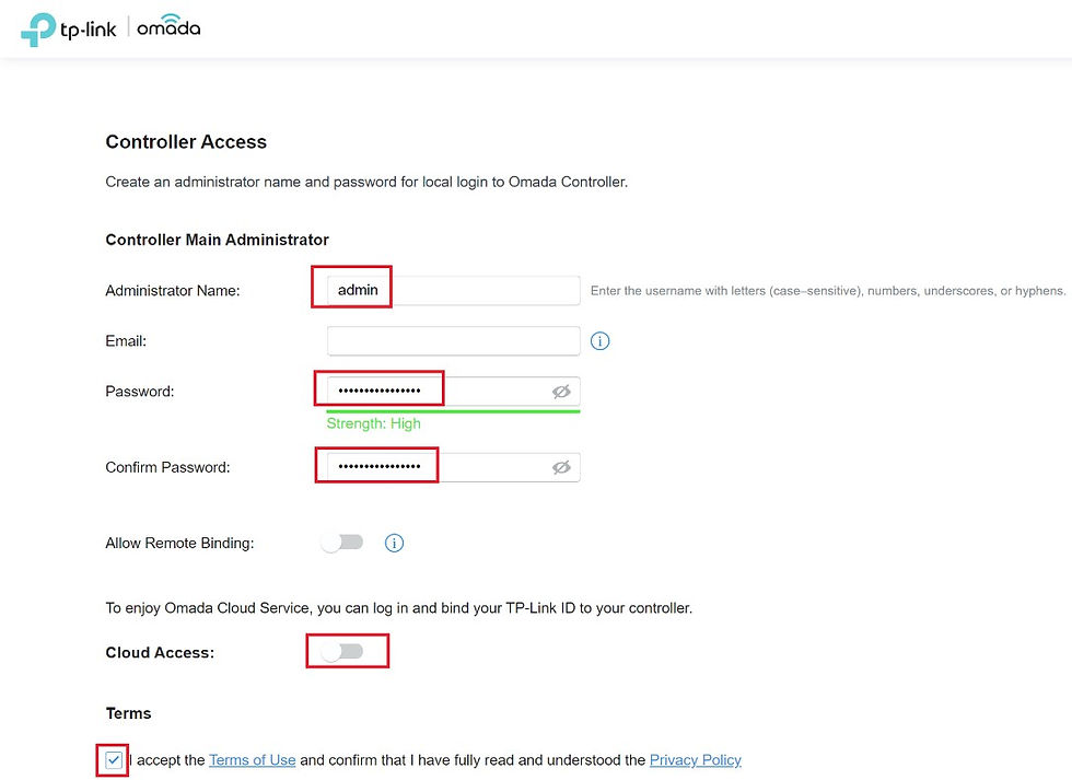
Fill up those boxes highlighted in red. No specific nomenclature for administrative name and password, up to personal preference. Disable "cloud access" for now (you can set it up at a later stage) and check the acceptance of terms and conditions box.
Set a name for your Omada controller (No specific nomenclature) and respective country and timezone. Lastly, select the appropriate application scenario which I do not find it changes anything downstream.

Since no other Omada devices (e.g. switch) are connected to the router, thus, can click "Skip" or "Next" to continue.

As I was been issued with an ONT from my ISP running on dynamic WAN IP, I will leave all settings at default. Click "Next" to continue.

As there isn't any APs connected to the router, click "Skip" to continue.

Over here, you can have a different user name and password to your Omada controller. For simplicity, we will simply use the same user name and password for both Omada controller and router device.

Finally, you have reached the end of the initial/administrative setup whereby a summary will be presented as follow.

Setup #2 - Editing default LAN settings
After initial setup, by default, a subnet will be created @ 192.168.0.1 which cannot be deleted but it does allow modification which we will be doing so in the following steps.
Click Settings (gear like icon right at the bottom left of the page) as shown below

Follow by Wired Networks -> LAN -> Edit button

In editing the default LAN, we have changed:
Name of the LAN to something more readable
Change the default DNS (from ISP) to Cloudflare Family friendly DNS whereby it will block Malware and adult sites.
Optional - You can edit the DHCP range highlighted in green to some other value.
For example, you can set it to start from 192.168.0.10 and with such a setup, you are essentially reserving some IPs for static IP purposes. In this case, you can have 192.168.0.2 to 192.168.0.9 (total 8 IPs) manually assign to other devices connected to the router.
Finally, click "Save" to save the settings.

Step #3 - Creating a new LAN network for CCTVs
Click Settings (gear like icon right at the bottom left of the page) -> Wired Networks -> LAN -> + Create New LAN
After inputting the Gateway/Subnet with 192.168.10.1/24, do remember to click on "Update DHCP Range" button whereby it will auto-fill the DHCP range.
A question arises on whether should I check ALL the boxes under LAN interfaces since the NVR is connected to port #12 only? In this scenario, yes, you can check LAN12 ONLY. By checking the boxes, it enables you to assign a PVID (Port VLAN ID) which is 10 in this case at another menu to the desired ports.
Finally, click "Save" to save the settings.

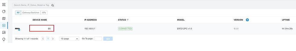
Click on "Devices" at the left most column and you should see the below screen. Thereafter, left-mouse click on the device name highlighted in red.
You should see a port overview popping out on the right of the page. Click on "Ports" section and locate port #12 and click on "Edit" icon.

Select 10 (from drop down box) @ PVID section. Click "Apply" to save and complete the settings. Any devices connected to port #12 will be assign with an IP 192.168.10.xx and a VLAN ID of 10.

Let's do a pitstop and you should have the following summarized view after completing the above steps. Check the name of the network, subnet and VLAN IDs.

Step 4 - Setting up security measures
The objective of Secure LAN network will the office's main network where we want to keep it secure and prevent unauthorize access while IPCam network is simply all the CCTVs feeding the footage to the NVR connected to port #12 in another network.
So the objectives of the security measure will be as such:
Prevent any devices connected to port #12 (a.k.a IPCam network) from accessing the Secure network. However, we still want to be able to access (from Secure network) to the CCTV footage stored at NVR connected to the IPCam network.
Prevent any devices connected to port #12 from accessing the management page/web GUI.
By default (without any rules setup), both Secure and IPCam is able to communicate with each other (though both are on different subnet) which will be illustrated as below.
Before performing this test, if you are using Windows desktop/notebook, by default, Windows firewall (a.k.a Windows Defender) will block ALL pings from different subnet. As such, you need to disable your Windows firewall before carrying out the test.
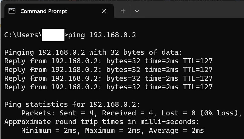
Desktop IP - 192.168.0.2 @ Secure network
Notebook IP - 192.168.10.2 @ IPCam network
Perform a ping from Desktop to notebook (successful)
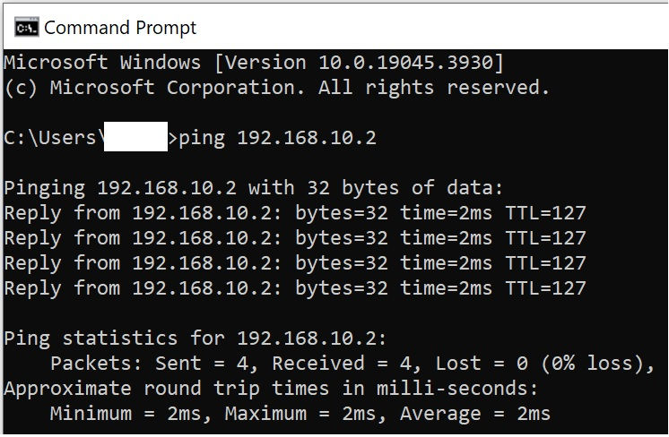
Perform a ping from notebook to desktop (successful)
Setup for objective 1 - Unidirectional access from Secure to IPCam network
Click Settings (gear like icon right at the bottom left of the page) -> Network Security -> ACL -> + Create New Rule

Now, perform the same ping test from Notebook (IPCam LAN) to desktop (Secure LAN) - Expected behaviour after turning on the newly created ACL rule.

Setup for objective 2 - Disable management/web GUI access from IPCam LAN network
Click Settings (gear like icon right at the bottom left of the page) -> Network Security -> ACL -> + Create New Rule


Using a browser, try accessing the router management/web GUI page

Check internet is still working fine despite the block to management/web GUI page

Summary
So yes, you have completed all the setup and ready to deploy into your office. Do note that the above setup is based on wired connection. In the coming update, we will add wireless AP into the setup. In terms of security and LAN partitioning, it doesn't differ much from the wired setup. Stay tune!


Comments